 |
| August 13, 2013 | Volume 09 Issue 30 |
Designfax weekly eMagazine

Archives
Partners
Manufacturing Center
Product Spotlight
Modern Applications News
Metalworking Ideas For
Today's Job Shops
Tooling and Production
Strategies for large
metalworking plants
Engineer's Toolbox:
New twist in wind blade design promises higher energy output
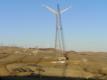
Figure 1. Sweep-twist adaptive rotor (STAR) prototypes were installed on a Zond 750-kW turbine at the TerraGen wind site in Tehachapi, Calif. Note the aft sweep of the tip and the trailing edge curvature of this innovative blade design.
The basic physics and economics of wind turbine blades are relatively simple. For one, their power output is roughly proportional to the square of blade length. This relationship pushes designers to create increasingly longer blades for harvesting additional kilowatts. Secondly, as blades get longer, weight increases -- by approximately the cube of the length -- leading to higher raw material costs. This correlation sends designers in search of weight-efficient geometries that are strong and rigid enough to weather the increased loading inherent in longer blades.
Navigating a maze of engineering challenges such as these can lead to interesting design directions. At the United States Department of Energy's (DOE) Wind Energy Research Program at Sandia National Laboratories, the result has been the development of a sweep-twist adaptive rotor (STAR). This innovative curved blade was proposed in earlier theoretical research and had been garnering increasing interest for use in utility-scale applications. The new configuration is seen as a way to reduce operating loads on ever-lengthening blades. If successfully commercialized, the outcome would be larger, lighter, less-expensive, and more productive wind turbines.
In 2004, Knight and Carver (K&C) Wind Group, a San Diego-based wind blade manufacturer, was awarded a DOE contract to develop STAR. Partnering with Sandia, K&C was responsible for design, fabrication, testing, and evaluation of a sweep-twist prototype. They began by assembling a team of specialized companies and academic institutions, one of which was Seattle-based NSE Composites, who were brought on board to perform the finite element modeling (FEM) of the new design.
"NSE had done a lot of analyses over the years on composite aircraft and helicopter aerostructures for companies such as Boeing," says DM Hoyt, one of NSE's founders. "Plus, we were already troubleshooting another blade problem for K&C and wanted to diversify our customer base to include more renewable energy, so the fit was a good one."
Hoyt and his partners at NSE have been using Abaqus from SIMULIA, the Dassault Systemes application for realistic simulation, as their finite element analysis (FEA) tool for years. As their projects moved toward larger and more complex models, the software's ongoing developments in simulating composites, crack generation, and fracture kept pace.
"Simulation has been a great asset for both our aerospace and wind energy work," says Hoyt. "It enables us to explore new ideas and look at the performance of multiple designs and materials while minimizing expensive testing."
Sweep-twist blade basics
Rather than a traditional linear profile, a sweep-twist blade has a distinctive, gently curving tip (or "sweep") with curvature toward the trailing edge (see Figure 1). Theoretically, this planform shape allows the blade to respond to turbulent wind gusts through a process of controlled twisting and bending: As the blade twists, it sheds loads that would normally be translated as material stresses to the root (or base) of the structure. In nature, a similar sweep can be seen in the wing shape of birds that migrate long distances and the characteristic profile of whale tails and dorsal fins.
The engineering upside of twist-coupling is the ability to create longer wind blades while avoiding the higher loads that typically accompany increased length. Reducing loading -- not only on the blade root but also on the turbine itself -- enables a lighter blade design with lower raw material costs and helps lessen fatigue stresses on the rotating machinery. In early calculations, the STAR design promised a decrease in fatigue loads of 20 percent using a tip twist of 3 degrees. But as the design progressed, longer blades that capture more energy with no increase in load were pursued.
Beyond the potential advantages of altering the traditional length-weight-cost relationship, twist coupling is seen as a financially attractive solution for tapping low-wind-speed sites (defined as having an average velocity of 5.8 m/sec at a 10-m height). These sites -- in contrast to the high-wind-speed locations that have been the focus of wind-mining to date -- are abundant in the U.S.' mid-section and closer to major power-load centers. If the cost benefit proves favorable, development of low-wind locations could increase potential domestic wind farm area by a factor of 20.
Understanding turbine behavior -- without the wind
"Over the years, wind blades have become more and more high tech. The industry is pushing the limits of design and materials," says Hoyt. "As that happens, engineers need to tighten up the loose legacy tolerances and manufacturing controls that originated in boat-building technology and adopt the more rigorous analyses that we have always done for complex aerospace structures."
Of particular use in wind blade analyses with FEA, notes Hoyt, is Abaqus' ability to handle composite properties and control material orientation. It can calculate blade-tip deflection (to avoid "tower strike") and accurately predict both torsional response (including twist angle, which is key to load shedding) and shear-compression buckling stability (associated with sweep-twist) of composite sandwich structures. An additional capability key to wind blade analysis is the extraction of accurate equivalent beam properties directly from a solid 3D FEM. These bending and twisting definitions are used in wind-blade-specific dynamics codes to predict the overall performance of the turbine.
"During the preliminary design phase, the type and amount of input data is often limited," says Hoyt. "In the wind projects we've been involved with to date, there hasn't been a high-fidelity CAD model available to use as a basis for the FEM." So at the start of the STAR analysis, the NSE team only had the blade's basic geometric parameters -- the planform shape, the airfoils, and the chord lengths -- to work with. The desire for high-fidelity FEA at a design stage when only the basic parameters of the blade have been defined led to the development of NSE's bladeMesher software, which is able to create a solid 3D mesh of the blade from the partial data.
"Our software splines the geometry defined at several locations on the outer mold layer (OML) of the blade and combines it with the composite material thicknesses specified at each location to generate a mesh with the true thickness details," says Hoyt. "This solid mesh and material definition is then imported into Abaqus where we perform a detailed finite element analysis. We have found that a solid FEM has many advantages over shell element FEMs, which have traditionally been used for blade analysis. These benefits include a more accurate prediction of twisting behavior and the ability to analyze stresses in the adhesive joints between structural elements."
As the design of the blade progressed, the team explored new airfoils and made adjustments to the sweep geometry to home in on the optimal amount of twisting. The bladeMesher software enabled rapid updates to the solid FEM based on the new geometry, allowing the team to quickly assess the effect of each change. Abaqus' task was to confirm the earlier section analysis predictions, which were performed using constant-section-equivalents to estimate the effective beam properties of the blade.
To determine whether the sweep-twist geometry would shed loads as predicted, two wind scenarios were applied to the model: an operating load and an extreme-wind conditions case (50-year gusts at 156 mph). The analysis was used to predict the blade deflection and twist, perform detailed stress calculations, and investigate potential shear buckling due to the increased twist inherent in the design (see Figure 2).
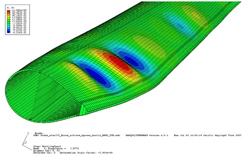
Figure 2. Post-processing of the Abaqus simulation allows users to see and understand potential buckling near the blade root.
For normal loads, there was excellent agreement with the tip deflection results from the section analysis. For extreme wind cases, strain value comparisons were also good. In further detailed studies, the engineering team found that their design met critical buckling limits at more than five times those of extreme wind conditions -- a large margin of safety driven by the fact that stiffness to limit deflection, rather than ultimate material strength, was the key structural criteria (see Figure 3).
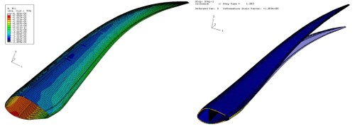
Figure 3. Abaqus FEA simulations illustrate stress/strain results for the STAR blade prototypes on the left (note the compression stresses on the upper, or low-pressure, side of the airfoil as the blade bends) and overall deflection results on the right.
Static physical testing of prototypes -- for shear strain, blade deflection, and twist angle -- followed FEA. The static test verified twist response under operating load conditions. Using fatigue testing, the K&C team was able to validate a 20-year lifespan for the new design, a timeframe equivalent to the current industry standard.
The prototypes were also field-tested, generating extensive data (as well as power) for several months in Tehachapi, Calif. -- site of the TerraGen commercial wind facility and also one of the largest wind-generation areas in the country.
A simple twist with major industry implications
With simulation and testing complete, the sweep-twist design's promised load-shedding response resulted in what Hoyt characterizes as a "very impressive" 12 percent power output boost over similarly rated turbines now in operation -- without load increase.
"I think it's the future of blade design," says Hoyt. "People are actively pursuing it." GE and Siemens, two of the biggest players in the industry, are currently developing swept blades. A start-up, Zimitar -- founded by researcher Mike Zuteck, who first conceived the sweep-twist design -- has just won a $4 million DOE contract to pursue the technology for bigger offshore turbine installations. Questions are in the air: Will it scale to a 50-m or 60-m blade? How will even longer blades respond?
At the Sandia Blade Workshop in spring 2012, engineers discussed possible downsides. Will torsional loading due to sweep introduce other problems like new modes of aeroelastic flutter? Or will it produce too much fatigue stress in the adhesive joints? There may also be issues on the manufacturing and transport side stemming from the harder-to-handle curved shape, says Hoyt. "But I wouldn't be surprised if in ten years a lot of production wind blades had some sweep in them.
"We use simulation all day, every day in our company. We can explore design space variables essentially with the click of a button and avoid a lot of early physical testing," Hoyt continues. "For example, using bladeMesher and Abaqus we can look at 20 different sweep geometries in a couple of weeks. If you were trying to evaluate all of those on a test rig, you'd be talking about a couple of years."
With all of the demonstrated benefits -- savings in design time, reduced testing, and increased power output -- this new twist on a traditional design is lining up to be a big win for wind.
Sidebar: A snapshot of STAR's composite makeup
At the STAR project's outset, total rotor diameter for the prototypes was set at 56 m (approximately 184 ft). Like most commercial blades, the STARs were to be fabricated using fiberglass and epoxy. Composite design included a stressed-shell approach in which the top and bottom shells are connected by a single shear web, rather than the more typical double web construction (see Figure 4). As the design went through numerous iterations over the course of the project, specific composite materials were carefully chosen for each blade feature.
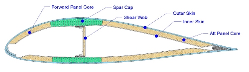
Figure 4. Cross-section of the prototype sweep-twist blade airfoil showing major composite construction features.
In the sweep-twist blade design version that NSE analyzed with Abaqus FEA, unidirectional roving was called out for the blade's spar caps, and double-biased fabric covering a balsa core was the choice for the shear webs and shell panels. For the skin, a mix of dual-biased and spanwise-oriented (along the length of the blade) unidirectional fabric was selected during preliminary design tests for its ability to follow the curvature of the blade during fabrication (see Figure 5). This combination increased the overall stiffness-to-weight ratio of the blade while improving torsional response -- a key factor in the twisting and load-shedding capability of the design. The maximum curvature at which fabrication and layup would become problematic from a material standpoint was also investigated.
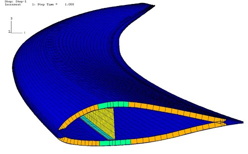
Figure 5. This Abaqus finite element model view illustrates how the unidirectional composite fabrics follow the curvature of the blade.
Want more information on Abaqus? Click here.
Published August 2013
Rate this article
View our terms of use and privacy policy